Boddo Mills Twin Rebuild Story

The name Mills is synonymous with fine model diesel engines throughout the modeling world and when this name is teamed with Boddington you know that we are talking about something very special. This is the story of my long battle to make a runner out of a sad example of a Boddo Mills Twin.
The name Mills is synonymous with fine model diesel engines throughout the modeling world and when this name is teamed with Boddington you know that we are talking about something very special. This is the story of my long battle to make a runner out of a sad example of a Boddo Mills Twin.


The great engine expert David Boddington created this little jewel back in 2006 when he took a pair of Mills 0.75 cc and joined them by an extended crankcase and shaft. A limited production run of Boddington's brainchild was done by China's CS Engines.

The Mills 0.75 is shown below for comparison purposes.

I bought my engine: described as new in box without serial number, which should have raised questions as to its authenticity but no, I thought that it must be a preproduction prototype, which should not be that bad.....could even be more valuable.

It wasn't until I attempted a test run, did I discover how wrong I was. The first thing I noticed was that the propeller kept slipping on the shaft; a closser look revealed a cracked prop-driver.

This story keep getting worse by the minute: after five short runs that couldn't have lasted more than 15 seconds the engine destroys itself and stops with a bang.

The rear cylinder lost 80% of its compression and the forward piston developed excessive play at the wrist pin.

The seller was very kind to immediately offer a new rod to correct the small end play problem, but in the end it would not have helped, because there were many more issues yet to be revealed. The small end of the rod was not wide enough as designed, only 3 mm through which passed a 2.5 mm wrist pin, which its self was cut too short. The present dimensions left only 0.25 mm per side at the best, not nearly enough under the circumstances, not forgetting the short pin. The stresses developed during running would assure almost no life before complete failure of the top end joint. With all this in mind I decided to make a 3 mm wrist pin from a needle bearing and dimension the rod's top end to provide plenty of meat for supporting this oversize pin, which will be cut off to the proper length.

After the new rods are installed in the crankcase more bad news is discovered: The rod lengths were actually too short. With one piston held at top dead center the other is allowing the crank chamber to vent and allow serious vacuum loss, which is shown clearly in the following pictures.


Here we can see that with the front cylinder at TDC the rear liner is opening up and light is coming through (vacuum leakage) which would not be a problem for a single cylinder engine but for twins with only one one shared carburetor it can be a real problem.

I decided to make a set of new longer connecting rods, 1.3 mm longer to alleviate the loss of vacuum problem. I used tempered AL2014 aluminium alloy, which is known for its strength (ultimate tensile strength 427 MPa or 62,000 psi) to make the new rods.


Below at right we show one of the new rods with 3 mm wrist pins with their 4.30mm wide lug ends, to accommodate the larger pins and allow plenty of extra material around the holes.


At this time I decided to move the front piston to the rear cylinder because it was a tighter fit and for the front cylinder I will make a completely new piston.

Below is pictured the almost complete new piston for the forward cylinder.


Below left the old piston with its short pin and undersize rod with the new combination shown on the right.

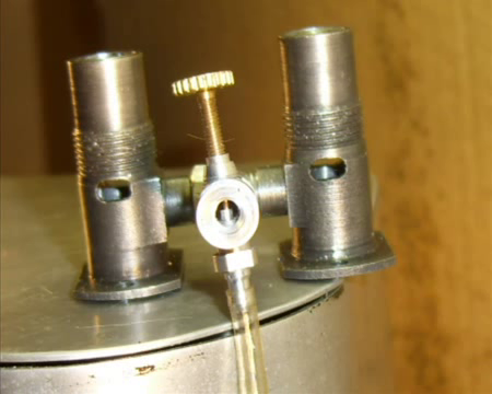
In the next picture we can see the Mills patented intake arrangement with the characteristic two closely placed holes, intended for better fuel atomization.

I decided to go one better and add another hole, since I figure it can't do much harm and more of a good thing may even be better; at any rate its nothing to add another small hole.

It was at this point that I noticed another strange thing: the rear liner was made with 40% less transfer channel area than its front counterpart.

Maybe it wasn't a mistake after all; just a lazy way to take the load off the front crank pin. This is not a problem any longer so I now have equal size channels in both cylinder liners.

During the assembly stage I discover more bad news: the crank has far too much play in its journals.

By pulling and pushing on the connecting rod a TDC the shaft moves up and down appreciably.

Still more problems and work for me: the heads of the cylinder hold down screws are fouling on the sides of the cylinder liners, thus preventing them from seating on the flange and holding the cylinder firmly to the crankcase, so the heads have to be turned down on the lathe to correct this problem; a simple but time consuming task to be sure.

Now no more fouling and everything is seating as intended.

Now when we turn over the engine we hear equal breathing noises coming from each cylinder.

But the stream of bad news seems to be endless: now its the carb; the tube inside diameter is extremely small and to make matters worse, there is no necking down to increase velocity at the section where fuel is being introduced, which is essential for good fuel draw and atomization according to Bernoulli's principle (p1v1=p2v2).


Yet another problem is the fact that the fuel tube is not positioned in the center of the throat where it should be, but rather is located at the bottom where the airflow is turbulent at the best.

The tube diameter is opened up as the first step as shown below.

Then I enlarged the ends to produce a conical opening to simulate the venturi shape.

To reposition the spray-bar and locate it at the proper location (the middle of the throat, I made a special insert.

Later I had to enlarge the throat and reduce the fuel tube inside diameter because I now had too much suction and it was flooding the engine.

I also made a new connecting tube because the threat was getting bad and the original tube was made just a little too short.

While I was at it, I made two crankcase covers and gaskets because I noticed air bubbles coming from this joint while running.

Next surprize! After a few short runs. the engine came to a sudden halt with a big bang.....OK what next? The shaft must have broken....or worse....how bad can it be? Taking it apart again and looking inside we are relieved to find that it is not broken, but simply unscrewed itself while running.

At least now I know how the shaft was made: in two pieces and joined with a left hand threaded joint which is locked by a hexagonal screw from the other side, but unfortunately no loctite was used on the threads..

The two sections of the shaft were also not aligned properly; which explains why it ran better in the opposite direction.


Finally- after countless hours of work, which included many setbacks; David Boddington would give his green light for a test run.

I am sure that David Boddington would never have sold an engine like this: with no serial number it must have been a pre production prototype or a proof of concept item and sold through the back door so to speak.


Watch the rebuild engine run for the first time.
Published on 1 Dec 2013
http://www.youtube.com/watch?v=WRUYiYAAmuQ