This posting is by Peter Valicek
and is based on his engine rebuild video wich was published on Youtube.
Sept 7 2015
Check out the full length Youtube video below.
Sept 7 2015
Background:
The subject of this rebuild story is a battered and broken FROG 500 glow engine from 1949.
At that time in Europe the model engine field was dominated by the compression ignition type commonly called a diesel engine, such as the popular ED Bee pictured below.
In 1948 FROG began studying what was happening in North America and in paticular the developments in progress at the K and B organization emboddied in their Torpedo glow/spark ignition engine.
FROG's first glow engine was released to the market some time between the end of 1949 and March 1950.
The bore and stroke of the new engine where 0.750 inches (19.05 mm) and 0.680 inches (17.27 mm) respectively.
The engine was sold as a glow plug engine but the crank shafts included a cam section that made it adaptable for spark ignition.
The rebuild story:
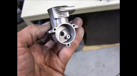
Pictured below are the rebuild candidate with its ugly venturi insert and and a diesel version of the 500.
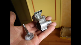
Parts awaiting a cleaning and final disassembly before starting work on the rebuild.
Parts layed out showing the broken crankshaft which is to be duplicated to form a replacement shaft.
Dimensions of the shaft as measured from the broken orginal are shown in the sketch below.
The source of material for the new shaft is an old drive axel from an automotive product. It was chosen because it is hardened steel and of close to the right maximum diameter for our crankshaft.
Pictured below are the sections of the broken shaft which remind us of the target dimensions for this turning process.
Because the material is very hard the process involves removing only 0.01 milometer per cut.
Below: showing the shape of the of the cutter.
A closeup view of our new lath which permits us to take on jobs like machining model engine crankshafts.
The turning process has taken approximately an hour to arrive at a diameter close to target size.
Checking that the diameter of the old shaft is 9.39 mm.
The new shaft now is measuring 9.70 mm.
The decision was made to cut the propeller shaft threads by hand, but first the thread type and size of the old shaft needs to be established.
Close examination and trial and error establishes that original thread is not a BA but a BSF 1/4 26 threads per inch.
Checking the old thread with a 1/4 26 die to assure that we have the correct die for the job.
The completed thread is shown below.
Grinding the journal portion of the shaft so it will fit snugly into the crankcase journal.
Checking the journal section for high spots.
Checking for excessive drag in the crankcase journal.
Measuring the depth of the crankshaft bore of the original shaft with digital calipers in the following 3 pictures.
Next step is to drill the air intake passage way.
Next step is to set the throw of the crank (stroke) which is 17.27 mm which is 2 times 8.64 mm approximately. To do this we have to establish the center of the crankpin for its turning.
We still have the eccentric holding fixture from the last job, so we just have to drill it out slightly to accept this new shaft.
Then make a change in the settings of my independent chuck because the holding tool's stroke was a little smaller than this current job.
I use here a small pilot hole to approach the correct offset dimension more easily.
After establishing the correct offset we begin to slowly begin machining to form the crank pin.
Slowly but surely the crank pin begins to take form.
Viewing the process from another angle.
Finally grinding the pin's surface to a smooth finish.
Now at its final target dimension and finish we test it for fit and function with the engine's connecting rod.
A visual comparison of the new shaft and the old broken one.
The next step is to find the correct location of the intake bore in relationship to the crank pin. I used a dividing table to establish this angular dimension. First we establish top dead center (TDC) position and set the ring to zero.
Then by turning the old shaft to the intake bore we read the angular displacement to be 55 degrees clockwise from the rear.
Now marking that position with a small center drill.
As always our motto is:
Drilling the intake hole to final size and surface finishing it to remove all burrs and tool marks.
Since this hole is an extremely high area of stress concentration (two intersecting holes) a smooth finish is very important step in avoiding a fatigue failure as was the the possible cause of the failure of the old shaft.
The last step is a final polishing and the new shaft is ready for service.
The next thing to get rid of is that very ugly venturi insert which we do by a process of heating and twisting.
Now we are ready for a good cleaning of the crankcase.
This cleaning was accomplished by a process of cooking the parts in brake fluid a a temperature of 80 degrees C for a period of a couple of hours.
Now the engine crankcase is shining like new.
As a final nice touch we blackened the screws and prop driver.
The small crack in the air intake was eliminated by filling it with liquid metal.
I made also a new copper head gasket of very thin material.
But it was impossible to get a good head seal since there was a casting line in the head so we resorted to making a gasket of asbestos which worked very well.
As a last step I needed to make a new spray bar and needle assembly, as close as possible to the original engine's
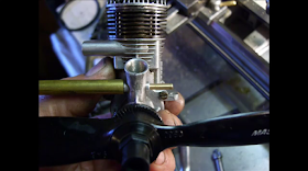
Click on the video to see how the rebuild ran on the teststand.
Check out the full length Youtube video below.


