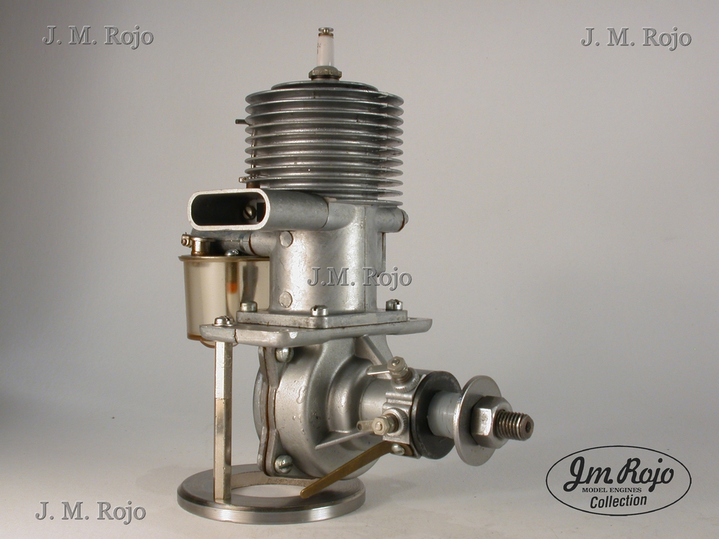


The Forster 99 ignition engine first appeared on the market in 1936 and was sold through the 1950's. Many features of the day included two speed timer to allow a low/high speed by retarding the spark timing, ball bearing crankshaft, and bronze bushed connecting rod. This well known favorite of many modelers produces .68 horsepower and swings a 14 to 16 inch propeller with ease.
Motor FORSTER 99 M & G Speed 2
Technical data :
Model FORSTER 99
Series / Serial Numbers s / n
Year of manufacture 1955
Displacement 0,997 cu. in. (16.33 d.c.)
Bore 1.062 in diameter. (1 1/16 in. 'S 26,975 mm.)
Stroke in 1,125. (1 1/8 in. 'S 28,575 mm.)
Spark ignition type
Cycle 2 times
Fixed Type carburetor (no regulation of speed)
Admission Sub-piston (port side)
If bearing Inner
Outer Bearing In
The crankshaft on the crankcase
If ERMEC on Crankshaft
Fuel Gas / (optional: Methanol )
Condition good used
Beam mounted Motor without plastic fuel tank. Spark plug 3/8 x 32. Piston with the rings. Timer a set of double platinum points, So that "b" or "a" timer can be chosen for low speed or high speed running (equivalent to continual motor control).
Engine operating tips
Ignition Set-up


Shown above is the RC activated switch for selecting high or low speed timers
The first thing I noticed when attempting to mount this big engine to the workbench was, because of the extra large diameter of the crankcase some sort of special mounting setup would be required. The workbench was a top consisting of a single piece of 2 inch thick Canadian Ceder measuring 2 feet by six feet in length so there was no real danger of the table top taking to flight during the test run. Our first attempt of attaching the Forster 99 involved using a two foot length of 2 X 4; notched to accommodate the crankcase and the mounting lugs secured to the 2 X 4 by 4 - 3/16 X 1.5 inch wood screws and the whole mount assembly screwed to the table top by 4 - 5 inch long number 10 deck screws.
The plan was to make the first few runs on this new to me engine using nitro fuel and glow plug ignition. After a healthy priming of the cylinder the glow driver was attached we stood to one side and gave the 17 X 8 inch prop a smart flip with an oak chicken stick. The engine fired up immediately, gathered speed and promptly departed the test stand trailing the length of fuel tubing.
After the initial shock subsided I set off to track down the resting place of the big Forster. The first clue that we were on the right track was the short length of brightly colored fuel tubing lying in the undergrowth 25 feet from the bench. I took this as an encouraging sign because finding objects in the woods can be a problem and at the best take a long search. Another 15 feet into the bushes we spotted her with mounting screws still attached: luckily the fuel tank was left on the bench otherwise she now would be lying in the next county.
The experience gave me cause to rethink the mounting setup and to conduct my activities from the opposite side of the bench: well out of harms way and out of range of that mighty spinning prop.
At this point I haven't been able to manage a full ignition run. The timer I selected to wire for the attempts appears to be the high speed one. I know this because the only firings were a few of those propeller throwing bangs that result from early ignition (well before top dead center). Tests with a multi-meter confirmed that the timer chosen is the one where the points first close in the cycle.
Now that I am almost certain which of the timer terminals is for the slow speed running (retarded setting; the plan is to select it for starting and have a double pole switch for selecting the high speed timer after starting and adjusting the fuel mixture. The timing adjustment arm is so close to the propeller arc that any running adjustments are just far too dangerous.
After several exciting runs of this engine using glow ignition and nitro fuel its time to move on and attempt running on full ignition and eventually; full ignition gasoline and speed tests with that two stage timer, but first we have to be able to identify which is the retarded timer for start-up.
Since we were not successful in making the old girl run on full ignition because the points could or would conduct the required current amperage I am thinking that its time to find a power transistor and make up a circuit to trigger the coil with a low current signal from the points.

Closeup views (top and bottom) of the two speed Foster 99's timer.


The transistor type above is PNP (current flowing from Emitter to Base)
This circuit is the circuit Bill Schmidt designed in the early 1980's. It is a time proven and reliable ignition system.
Use TIP42, 2N-5195, or SK series (SK-3083, SK-3189, or SK-3961) transistors.
Make sure you use the 10K ohm resistor at the spark plug on radio control ignition models or excessive radio interference will result.
The limiting resistor from the base of the transistor to the points should be between 18 and 22 ohms, or the trigger current can be excessive causing burning of the points. (This electronic ignition reduces deterioration of the points greatly compared to the old points-condenser circuit.)
Use a new strong coil as some other older coils don't work well in a transistor driven circuit.
Use 16 gauge wire or bigger from the battery to the coil or excessive voltage drop will reduce spark effectiveness.
You can use 3 nicads, 3 nickel metal hydroxides or 2 dry cell batteries for the battery source. Make sure you have between 3.0 and 4.0 volts at all times.
An external boosting battery source can be used to give a hotter starting spark, but is usually only needed when using dry cells. Parallel the booster battery across the model battery using a plug and jack.
The kill switch can be activated by timer or servo depending on the application.
I purchased a bag of 5, 2SK2850 K2850 transistors on eBay for five dollars and now I am ready to build a electronic ignition circuit for the Forster 99 armed with a few facts* about power transistors.
After a successful running session of this old brute using nitro fuel and glow ignition I thought it may be interesting to try a run on full ignition. I experimented for some time to identify the three leads of the tansistor, even made a few guesses and wired a transistor into the circuit taking care to chose a new one each time, to eliminate the possibility that last trial had somehow damaged it. I had no luck with this process and after I thought about it for a while I realized that there were factorial 3 possibilities (3X2X1=6), I gave up and decided to try a run without it.
Here is a video of the results of this attempt.
*
SOME PRELIMINARY FACTS:
There are no "fixed" pinouts for the leads of some transistors. But in general there is a "common" pinout for each style of case. Most technical data sheets include a pinout diagram but if the transistor is unmarked or
unknown, what do you do?
Simply follow our 3-step approach:
Firstly, the transistors we are talking about are "ordinary" transistors.
The technical name is Bipolar Junction Transistor (BJT) (other types of transistors are: Field Effect Transistors, Uni-Junction Transistors,
and others).
"Ordinary" transistors have three leads:
and come in many different styles and cases.
| Identify COLLECTOR, BASE and EMITTER |